Pressure losses: the importance of being able to read technical diagrams and tables
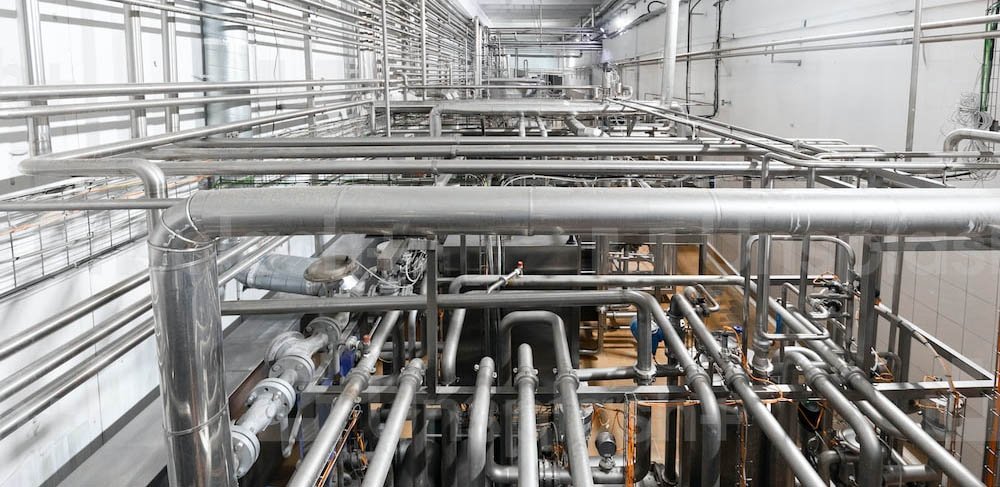
When designing a plumbing system, it is very important to consider pressure drops or pressure losses because hydraulic efficiency and even energy savings depend on them.
- Fluid dynamics generate in unavoidable pressure loss along the water network.
- Pipeline length and diameter, velocity and coefficient of friction: there are many factors to consider
- It is important to consider both distributed and concentrated pressure drops
- Diagrams and tables make it easier to calculate pressure drop and help practical system design
Tables and diagrams for pressure drops: an aid for the designer
Pressure drop is a phenomenon found in every hydraulic circuit. In fact, it is the dynamics of fluids themselves that result in pressure loss either due to generalized friction throughout the flow network or due to the presence of elements-for example, a valve or a bend-that cause resistance to flow. In the former case we speak of distributed pressure drops, in the latter case of localized pressure drops.
When designing a plumbing system, it is essential to take load losses into account and calculate them accurately. This is the only way to correctly size the system and guarantee the required flow rate.
For this purpose, there are tables and diagrams that allow you to measure pressure drops and design your system efficiently accordingly.
Distributed pressure losses: determinant factors
Regarding distributed pressure drops, some basic concepts can be identified.
Pressure drop corresponds to the potential energy lost as heat by the fluid to overcome the friction encountered along the pipeline.
The pressure drop depends on the size of the pipeline (length and diameter), the viscosity and velocity of the fluid, and the roughness of the inner surface of the pipeline. Specifically, the pressure drops are:
- directly proportional to pipe length: they increase with pipe length;
- inversely proportional to the square of the radius of the cross-section: if the diameter decreases, pressure drops increase significantly with the same flow rate;
- directly proportional to fluid velocity: the faster the fluid flows, the more energy is dissipated. For the same pipe diameter, the greater the velocity, the greater the pressure drops;
- directly proportional to fluid viscosity and piping roughness.
Coefficient of friction and Moody's diagram
The formula that puts all these elements together is Darcy's law. According to that formula, the pressure drop is given by the ratio of the product of the square of the velocity times a drag coefficient or friction factor and twice the diameter of the pipe. The drag coefficient, in turn, is a function of the roughness of the pipe and the Reynolds number, a dimensionless value proportional to the ratio of inertia forces to viscous forces. It is the Reynolds number that makes it possible to distinguish between laminar or turbulent flow.
To find out the coefficient of friction, the Moody diagram can be used. In it the abscissae show the values of the Reynolds number, the ordinates the value of the coefficient of friction, and the different curves the values of roughness.
What is the utility of the Moody diagram?
Knowing the value of the Reynolds number and knowing the relative roughness of the pipeline, the diagram allows the determination of the friction factor, which in turn allows the calculation of distributed pressure losses.
Of course, to facilitate the calculation of pressure drops, from the physical laws and related formulas, ready-to-use tables and diagrams have been created. Generally, pressure drop diagrams are developed on a logarithmic scale and show pressure drops on the abscissae and flow rates on the ordinates. Pipe diameters and water velocities are represented by bundles of straight lines perpendicular to each other.
When pressure drops are localized
Along with distributed pressure drops, it is also necessary to consider localized or concentrated pressure drops. The physical principles determining pressure drop do not change, and the method of equivalent lengths can be used for calculation. Basically you match the concentrated pressure drop to the length of pipe that would give the same pressure drop. A more precise method, however, is to use the Kv or flow coefficient.
This coefficient defines the flow of water through the component with a pressure differenziale di 1 bar, mettendo quindi in relazione portata e perdita di carico.
This coefficient defines the flow of water through the component with a pressure differenziale di 1 bar, mettendo quindi in relazione portata e perdita di carico.
Tables with flow coefficients for the main components of hydraulic networks are available. However, it is important to consider that the type of product can make a difference. Not all hydraulic valves, for example, have the same flow coefficient. There are valves that provide minimal pressure drop and consequently can significantly affect energy savings.